Tuesday, 15 January 2013

ODSS Electric Car Team

     For the previous years at my school, I have taken part in the electric car team. The purpose of the team is to design and build efficient electrical race cars. Generally, each year we revamp or scrap one of the older cars we have, and build a new car, with improved and refined technology. 


      Near the end of the school year, there are several competitions that allow us to compete with other high schools. There are 2 events that take place: the 12 volt race, and the 24 volt race. In the 12 volt, each car must draw power from a single 12 volt car battery, and complete as many laps as possible within one hour. The car that completes the most laps wins. In the 24 volt, each car is powered by 2 car batteries, and as such, the cars have plenty more power and lifetime, making a skilled driver much more important. Speeds in the 24 volt can reach up to 70km/h. In 2010, 11 schools from eight different school boards visited ODSS for this year’s annual electric car competition, which will test the distance traveled by each vehicle in 12-volt and 24-volt competitions. In 2009, Mr.Weishar, our teacher and team leader said the 24-volt winning car covered 38 kilometers in an hour while the 12-volt winning car traveled about 31 clicks.


       In this picture here, from 2010, you can see 3 of the cars built by our team. In the front, number 64, is one of the older models we have. It has a Styrofoam and fiberglass body and focused on maximum aerodynamics. That car is currently being revamped to more advanced standards this year. The next car, in the middle of the shot, number 21, was a successful experiment, in that we made the car as small and as agile as possible. The steering control was the same as an ATV, as in a handlebar that gave the driver more leverage than a steering wheel. That car has done quite well in competitions, all though it has the tendency to roll over at high speeds. Finally(and in the picture below), in the very back is the car we affectionately named 'The Tank'. The idea behind it was to have a heavier body, with a much stronger motor. We found it to be quite troublesome to build, quite hard to control, and overall severely sluggish. as such, it was scrapped for parts at the end of that year. The car that was built in 2011 is of course not shown here, but I'll mention it anyways. It uses a very smart boost power system, where a smaller motor powers the car around turns and other situations that call for agility, but on straightaways, the driver activates a much larger motor for a very powerful speed boost. So far, it has placed fairly high in the competitions it raced in. 
The Team was featured in the local paper during
 the 2010 competition that took place in Orangeville

       Overall, I have highly enjoyed being part of the team, and have learned quite a lot about design and innovation from it. It has given me a large understanding about the design process, and taught me skills that I will be able to carry with me throughout my life.

Wednesday, 2 January 2013

Raspberry Pi and Robot Plans

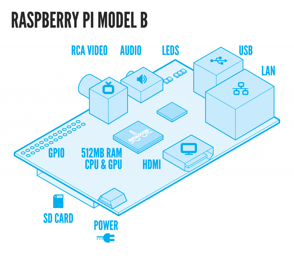
          Allow me to show you the Raspberry Pi. It's a very capable computer for its size, just a bit larger than a credit card. The point of it is to introduce programming to kids, to help them build fundamental skills for a career in software engineering. The problem that the makers of this found was that kids were entering post-secondary education with less and less understanding of computers and software. Previously, kids would learn about computers by playing around with simple platforms like the Commodore 64. So the Raspberry Pi was created, a small computer built specifically for hobbyist programming. At its heart is a ARM11 chip, which gives it roughly the same computing power as a first generation Xbox or Playstation. It has 2 usb ports, one for a keyboard and one for a mouse, a lan socket, a mini usb plug to power it with a 5V power source, an RCA and HDMI port for video, and a SD-card slot that it uses for memory.


     My plan for the Raspberry Pi is to combine it with my robot arm to give it some autonomous abilities. The Pi appears to have the necessary features to communicate with the arm, and if it could be put on a chassis along with the arm, then we it would be able to roam around without the need to be connected to the stationary mac. We could write simple programs that would allow the arm to move around and interact with it's environment, such as picking up an object, or moving through a cluttered space by moving debris out of the way. We have also purchased an infra-red sensor, that can be used as a type of electronic eye that the robot can use to judge distances, as demonstrated by this video:
         For the actual frame of the robot, I was planning to make the simple chassis out of wood or lego, big enough to hold the robot arm, Raspberry Pi, a breadboard to connect the two, and the power systems, which will consist of a battery and circuitry to power the SSC-32 card the Raspberry Pi and the servos at the voltages they require. Initially we can just provide power via a cable to the AC power supply. We will also have to figure out how to make a serial data connection between the Raspberry Pi GPIO pins to the TTL Serial Port on the SSC-32 because they are different voltages. I want the robot to look a bit cleaner than just a chassis covered in wires and circuit boards, so I would like to use thin sheet metal to build an outer shell for it, to give it a more professional look.

Tuesday, 25 December 2012

Receiving Info From the Servo Motors

      Since we successfully sent commands to the controller using the sliders, our next endeavour was to get feedback on the actual position of the servos as they move, using the commands Q & QP. The format of the Q command is "#(servo) Q", and it will send back an ASCII '+' or '.'. The plus means that the servo is currently in motion, while the period means the servo is stopped. The QP command takes the form of "QP(servo)", and will return the pulse width that the servo has been delivered. Using these 2 commands, we can track the servo as it moves.


      We added a text box to the right of slider 4 in our control window and modified our code to have the program show the current pulse width as the slider and the servo both move.
     Our first attempt at coding this was to add a subroutine called “getPulseWidth” that sent the SCC-32 the QP command for servo 4, then read the response and put it in the text box. This operated on roughly the same lines as how we sent sent the move commands to the arm, and then it used the 'read' command to get the signal that was sent back. Because the SSC-32 can sometimes take a few milliseconds to respond, we included a timer that pauses the program for 6 milliseconds to account for that. The program then converts the response to to an integer, and places it in the text box.


      This worked, but we wanted something that would constantly display the pulse width as it changed, not just once when the slider was moved. To do this, we used a loop to call “getPulseWidth” multiple times, constantly updating the text box. It kept getting the value but introduced a few other problems. Since that the loop was constantly running, it became somewhat of a power-hog, and was using processing power when we didn't need it to. This caused large amounts of lag, slowing down our program.

          To fix this,we used a special timer that would trigger every 5th of a second and check the pulse width. This worked perfectly but the timer was still running. We fixed this with the “Q” command, so that the timer when the servo stopped moving. It works by sending the Q command to the arm, reading the response, and if it's a period, meaning that the arm has stopped, it kills the timer.


      We also did one last check of the pulse when the arm had stopped to make sure we got a final position value. This ensured that the position in the text box was correct. We also had to add a couple of lines to kill the timer before we started it just to make sure that the timer was completely reset.


Here's a video showing the final program with the pulse value being updated as the servo moves:


Friday, 21 December 2012

Robot Arm: Writing The Controller

     Since my understanding of programming isn't overly advanced yet, the best approach to building a program for the arm would be to find a program that has a similar function, and modifying it for my needs. After browsing the apple forums, we found a program that someone had developed that could output signals from the serial port. 


       Using a programming environment called XCode, we opened up the program and examined it to figure out how it worked. We then stripped out all of the code we didn't need, leaving us with a solid foundation that we could build upon.


       From there, we built a simple interface consisting of six sliders that controlled each of the six servos. The program had to be written in a language called Objective C, which has some similarities to the Java programming language we used in my Grade 11 Programming course, so it wasn't that hard for me to understand.


       Here is a look at a portion of the code that handles the interface. The very first line basically waits for any of the sliders to be changed, and when one is, it activates the code within the curly brackets. The next line creates the format for the signal that will be sent to the robot(the red text). Normally, the signal that is sent to the robot is "#(servo) P(desired servo position) S(speed)". For instance, if you wanted to send the shoulder to position 1700 at a low speed, you'd type "#1 P1700 S100" and then hit enter. So in our program, you'll notice the same format, except the servo number and servo position have been replaced by a "%d", which is used in Xcode as a substitution, so you can get the program to replace that "%d" with any set of symbols, letters, or numbers. 

        The next few lines get somewhat complicated, but all they really do is take the decimal data received from the slider and convert it to ASCII, so the arm understands it. Finally, the last line outputs the ASCII command through the serial port.

Tuesday, 4 December 2012

Robot Arm: Testing the Computer


     To run the robot arm with a computer, we first needed to make sure the computer could send and receive signals. Since the Macintosh does not have a physical serial port, we used a USB to serial cable that we connected to the physical serial port on an older PC. Then, using terminal emulation programs, which allow you to send and receive signals out the serial port. We set both of the programs to accept ASCII characters, as that is what the robot arm uses, then successfully transmitted a signal to the PC using the Mac, with the same speed and conditions required by the robot arm(115.2kb/s, 8 bits no parity).


Here, you can see that the message that was written on the mac was successfully delivered to the PC using the terminal programs.

     We later used the same method to test if our simple program to control the arm was working. It was better to use the PC to test the program, rather than the arm itself, because we can actually see the signals our program is sending. We used RealTerm on the PC ( download at http://realterm.sourceforge.net ) and CoolTerm on the Mac ( download at http://freeware.the-meiers.org/#CoolTerm ). Both are free and work really well.

Monday, 19 November 2012

Welding cast iron brackets

     Today, 2 brackets that hold up a side shelf on our wood stove broke off, so i took them into welding class to see if I could fix them. I was worried they wouldn't weld well, as they are made of cast iron, and neither me, nor my welding teacher knew if it would work. To my surprise, I easily joined them with a MIG welder, and grinded the weld so it was flush with the rest of the piece, then polished it off. Here's a picture I took after I did the first one. It was much easier then I thought it would be, and I am quite pleased with the final product.

Sunday, 18 November 2012

Offroad Truck Bumper Part 1


     I've decided to build my own bumper for my truck that will increase it's capabilities, allowing it to be more agile over rough terrain. I've looked into buying a bumper, but there aren't too many available for the 97-03 generation of F-150s, and all the one's I've found are highly expensive. The style of bumper that I've chosen is prerunner/baja. These bumpers are widely used in desert racing and offroading in areas such as Mexico and Southern California.


The main point of these bumpers is to improve the clearance of the front end. Normally, if you were trying to drive your truck from flat ground onto a steep incline, the bumper would hit, and you'd get stuck. These bumpers expose much more of the wheel, thereby allowing the truck to handle drastic changes in incline.  


     To build my bumper, I would first need to find a way to mount it to my frame. The old bumper was bolted onto 2 large brackets that were welded to the end of the frame. To mount my bumper, I would need to chop the ends of the frame off to allow the skid plate to have shallower angle, which will keep air resistance to a minimum.


    First, I drew up some designs for the mounting brackets of my bumper. I then cut out the pieces I would need with a plasma cutter. I used 1/4 inch iron, as it would give my bumper a good strong base to sit on.


    I used a mig welder to join the pieces together, and once I had both brackets built, I arc welded a piece of tube in between them to get the width right.